
Page 264 - An Introduction to Microelectromechanical Systems Engineering
P. 264
Quality Control, Reliability, and Failure Analysis 243
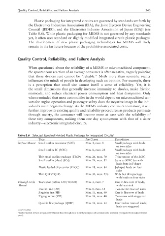
Plastic packaging for integrated circuits are governed by standards set forth by
the Electronics Industries Association (EIA), the Joint Electron Device Engineering
Council (JEDEC), and the Electronics Industry Association of Japan (EIAJ) (see
Table 8.6). While plastic packaging for MEMS is not governed by any standards
yet, it often uses standard or slightly modified integrated-circuit plastic packages.
The development of new plastic packaging technologies for MEMS will likely
remain in the far future because of the prohibitive associated costs.
Quality Control, Reliability, and Failure Analysis
When questioned about the reliability of a MEMS or micromachined component,
the spontaneous reaction of an average consumer is often negative, vaguely pointing
that these devices just cannot be “reliable.” Myth more than scientific reality
influences the minds of people in developing such an opinion. For example, there
is a perception that small size cannot instill a sense of reliability. Yet, it is
the small dimensions that generally increase immunity to shocks, make friction
miniscule, and reduce electrical power consumption and heat dissipation. Only
when reminded that most automobiles in the world depend on micromachined sen-
sors for engine operation and passenger safety does the negative image in the indi-
vidual’s mind begin to change. As the MEMS industry continues to mature, it will
further improve its existing quality and reliability procedures; as products permeate
through society, the consumer will become more at ease with the reliability of
these tiny components, making them one day synonymous with that of a sister
industry—electronic integrated circuits.
Table 8.6 Selected Standard Molded Plastic Packages for Integrated Circuits*
Type Pin Count Description
Surface Mount Small outline transistor (SOT) Min. 3, max. 8 Small package with leads
on two sides
Small outline IC (SOIC) Min. 8, max. 28 Small package with leads
on two sides
Thin small outline package (TSOP) Min. 26, max. 70 Thin version of the SOIC
Small outline J-lead (SOJ) Min. 24, max. 32 Same as SOIC but with
leads bent in J shape
Plastic leaded chip carrier (PLCC) Min. 18, max. 84 J-shaped leads on four
sides
Thin QFP (TQFP) Min. 32, max. 256 Wide but thin package
with leads on four sides
Through-Hole Transistor outline 220 (TO220) Min. 3, max. 7 One in-line row of leads,
Mount with heat sink
Dual in-line (DIP) Min. 8, max. 64 Two in-line rows of leads
Single in line (SIP) Min. 11, max. 40 One in-line row of leads
Zigzag in line (ZIP) Min. 16, max. 40 Two rows with staggered
leads
Quad in line package (QUIP) Min. 16, max. 64 Four in-line rows of leads;
leads are staggered
(Source: [25].)
*Surface mount devices are generally thinner than through-hole mount packages and accommodate a smaller spacing between adjacent leads
(pins).