
Page 46 - An Introduction to Microelectromechanical Systems Engineering
P. 46
Important Material Properties and Physical Effects 25
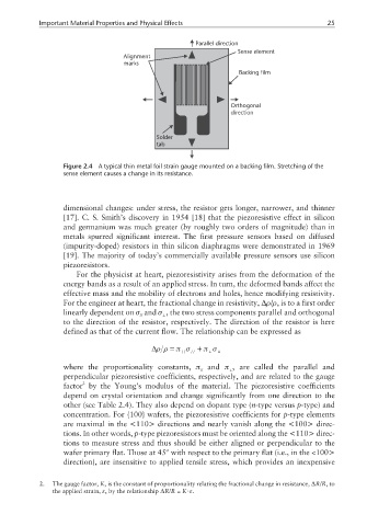
Parallel direction
Sense element
Alignment
marks
Backing film
Orthogonal
direction
Solder
tab
Figure 2.4 A typical thin metal foil strain gauge mounted on a backing film. Stretching of the
sense element causes a change in its resistance.
dimensional changes: under stress, the resistor gets longer, narrower, and thinner
[17]. C. S. Smith’s discovery in 1954 [18] that the piezoresistive effect in silicon
and germanium was much greater (by roughly two orders of magnitude) than in
metals spurred significant interest. The first pressure sensors based on diffused
(impurity-doped) resistors in thin silicon diaphragms were demonstrated in 1969
[19]. The majority of today’s commercially available pressure sensors use silicon
piezoresistors.
For the physicist at heart, piezoresistivity arises from the deformation of the
energy bands as a result of an applied stress. In turn, the deformed bands affect the
effective mass and the mobility of electrons and holes, hence modifying resistivity.
For the engineer at heart, the fractional change in resistivity, ∆ρ/ρ, is to a first order
linearly dependent on σ and σ , the two stress components parallel and orthogonal
// ⊥
to the direction of the resistor, respectively. The direction of the resistor is here
defined as that of the current flow. The relationship can be expressed as
∆ρ ρ= π σ + π σ ⊥
⊥
//
//
where the proportionality constants, π and π , are called the parallel and
⊥
//
perpendicular piezoresistive coefficients, respectively, and are related to the gauge
2
factor by the Young’s modulus of the material. The piezoresistive coefficients
depend on crystal orientation and change significantly from one direction to the
other (see Table 2.4). They also depend on dopant type (n-type versus p-type) and
concentration. For {100} wafers, the piezoresistive coefficients for p-type elements
are maximal in the <110> directions and nearly vanish along the <100> direc-
tions. In other words, p-type piezoresistors must be oriented along the <110> direc-
tions to measure stress and thus should be either aligned or perpendicular to the
wafer primary flat. Those at 45º with respect to the primary flat (i.e., in the <100>
direction), are insensitive to applied tensile stress, which provides an inexpensive
2. The gauge factor, K, is the constant of proportionality relating the fractional change in resistance, ∆R/R,to
the applied strain, ε, by the relationship ∆R/R = K⋅ε.