
Page 49 - An Introduction to Microelectromechanical Systems Engineering
P. 49
28 Materials for MEMS
p i
p i
Σp= 0 Σp = 0
i
i
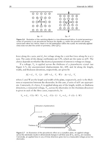
Figure 2.6 Illustration of the vanishing dipole in a two-dimensional lattice. A crystal possessing a
center of symmetry is not piezoelectric because the dipoles, p, within the primitive unit always
i
cancel each other out. Hence, there is no net polarization within the crystal. An externally applied
stress does not alter the center of symmetry. (After: [21].)
force along the z axis, and d for voltage along the z axis but force along the x or y
31
axis. The units of the charge coefficients are C/N, which are the same as m/V. The
choice depends on whether the electrical parameter of interest is voltage or charge.
If a voltage, V , is applied across the thickness of a piezoelectric crystal (see
a
Figure 2.7), the unconstrained displacements ∆L, ∆W, and ∆t along the length,
width, and thickness directions, respectively, are given by
∆L = d ⋅ V ⋅ L t ∆W = d ⋅ V ⋅ W t ∆t = d ⋅ V a
a
31
33
a
31
where L and W are the length and width of the plate, respectively, and t is the thick-
ness or separation between the electrodes. In this case, d units of m/V are appropri-
ate. Conversely, if a force, F, is applied along any of the length, width, or thickness
directions, a measured voltage, V , across the electrodes (in the thickness direction)
m
is given in each of the three cases, respectively, by
V = d ⋅ F ( W⋅ε ) V = d ⋅ F ( ⋅ε L ) V = d ⋅ F t ( ⋅ε L W )
⋅
⋅
m 31 m 31 m 33
3 (Direction of polarization)
1
Length (L)
2
Width (W)
V
Thickness (t)
Electrodes
Figure 2.7 An illustration of the piezoelectric effect on a crystalline plate. An applied voltage
across the electrodes results in dimensional changes in all three axes (if d and d are nonzero).
31 33
Conversely, an applied force in any of three directions gives rise to a measurable voltage across the
electrodes.