
Page 113 - Analog Circuit Design Art, Science, and Personalities
P. 113
Analog Design Discipline
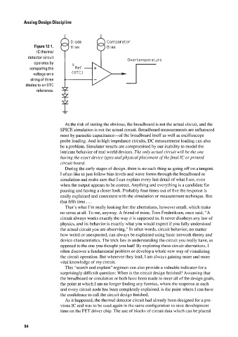
Figure 12-1.
IC thermal
detector circuit Overternper-aLdI e
operates by
comparing the Ref. -
voltage on a (OTC)
string of three
diodes to an OTC
reference.
f
At the risk of stating the obvious, the breadboard is not the actual circuit. and the
SPICE simulation is not the actual circuit. Breadboard measurements are influenced
most by parasitic capacitance-of the breadboard itself as well as oscilloscope
probe loading. And in high impedance circuits, DC measurement loading can also
be a problem. Simulator results are compromised by our inability to model the
intricate behavior of real world devices. The only actual circuit will he the one
having the e,t-uct device types and physical placement ofthe jinal IC or printed
circuit board.
During the early stages of design. there is no such thing as going off on a tangent.
I often like to just follow bias levels and wave forms through the breadboard or
simulation and make sure that I can explain every last detail of what I see, even
when the output appears to be correct. Anything and everything is a candidate for
pausing and having a closer look. Probably four times out of five the response is
easily explained and consistent with the simulation or measurement technique. But
that fifth time. . .
That’s what I’m really looking for: the aberrations, however small, which make
no sense at all. To me, anyway. A friend of mine, Tom Frederiksen, once said, “A
circuit always works exactly the way it is supposed to. It never disobeys any law of
physics, and its behavior is exactly what you would expect if you fully understood
the actual circuit you are observing.” In other words, circuit behavior, no matter
how weird or unexpected, can always be explained using basic network theory and
device characteristics. The trick lies in understanding the circuit you really have, as
opposed to the one you thought you had! By exploring these circuit aberrations. I
often discover a fundamental problem or develop a whole new way of visualizing
the circuit operation. But wherever they lead, 1 am always gaining more and more
vital knowledge of my circuit.
This “search and explain” regimen can also provide a valuable indicator for a
surprisingly difficult question: When is the circuit design finished‘? Assuming that
the breadboard or simulation or both have been made to meet all of the design goals,
the point at which I am no longer finding any funnies, where the response at each
and every circuit node has been completely explained. is the point where I can have
the confidence to call the circuit design finished.
As it happened, the thermal detector circuit had already been designed for a pre-
vious IC and was to be used again in the same configuration to save development
time on the FET driver chip. The use of blocks of circuit data which can be placed
94