
Page 55 - Analog Circuit Design Art, Science, and Personalities
P. 55
Reflections of a Dinosaur
vcc l+15 Volts1
7"
Eight
Rl Equally
12 K Weighted
N
CR2
MSB
lout*-
:+\
R15
1.0 K
R16
1.0 K
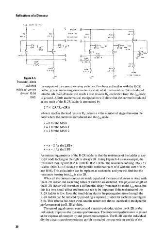
Figure 6-5.
Transistor-diode
switched the outputs of the current steering switches. For those unfamiliar with the R-2R
individual current ladder, it is an interesting exercise to calculate what fraction of current introduced
division 12-bit into the nth R-2R-R node will reach a load resistor RL connected from the IOut node
DAC. to ground. A little mathematical manipulation will show that the current introduced
at any node of the R-2R ladder is attenuated by
2-" X (2R/(RL+2R))
when it reaches the load resistor RL; where n = the number of stages between the
node where the current is introduced and the lout node.
n = 0 for the MSB
n = 1 for the MSB-1
n = 2 for the MSB-2
n = n - 2 for the LSB+I
n = n - 1 for the LSB
An interesting property of the R-2R ladder is that the resistance of the ladder at any
R-2R node looking to the right is always 2R. Using Figure 6-4 as an example, the
resistance looking into R35 is 1000 (n, R35 + R36. The resistance looking into R33
is also 1000 {I, (R33 added to the parallel combination of R34 with the sum of R35
and R36). This calculation can be repeated at each node, and you will find that the
resistance looking into IOU[ is also 2R.
When all the current sources are made equal and the current division is done with
the R-2R ladder, the switching times of each bit are matched. The physical length of
the R-2R ladder will introduce a differential delay from each bit to the Z,,,, node, but
this is a very small effect and turns out not to be important if the resistance of the
R-2R ladder is low. Even the small delay due to the propagation time through the
R-2R ladder can be reduced by providing a separate divider for each bit (see Figure
6-5). This scheme has been tried, and the results are almost identical to the dynamic
performance of the R-2R divider.
The use of equal current sources and a resistive divider, either the R-2R or the
individual, improves the dynamic performance. The improved performance is gained
at the expense of complexity and power consumption. The R-2R and the individual
divider circuits use three resistors per bit instead of the one resistor per bit of the
36