
Page 66 - Analog Circuit Design Art, Science, and Personalities
P. 66
Jim Williams
Figure 7-5.
My version of
Hewlett‘s circuit.
Distortion was
much better, but I
was fifty years
too late.
bration accuracy of 1%. The lamp maintained output amplitude stability within
0.2% at 100 cycles, varying only 1 dB from 20 to 20,000 cycles. Peering into my
HP 201, I can see the light bulb, just where Hewlett, or one of his assistants, left it.
Hewlett’s Figure 4 showed distortion well within 0.5% over the output range.
This distortion figure caught my attention. By contemporary standards, Hewlett’s
6J7/6F6-based “op amp” had major performance limitation^.^ How good, I won-
dered, would Hewlett’s basic circuit be with a modern op amp?
And so, some fifty years after Hewlett finished, I sat down and breadboarded the
oscillator to the meter of that Sunday afternoon rain. My circuit is shown in Figure 7-5.
This circuit is identical to Hewlett’s, except that I have managed to replace two
vacuum tubes with 94 monolithic transistors, resistors, and capacitor^.^ (I suppose
this constitutes progress.) After establishing the 430 R value, the circuit produced a
very nice sine wave. Connecting my (HP) distortion analyzer, I was pleased to mea-
sure only 0.0025% distortion (Figure 7-6). Then, I went ahead and endowed the
basic circuit with multiple output ranges as shown in Figure 7-7.
This also worked out well. As Hewlett warned, distortion increases as oscillator
3. For those tender in years, the 637 and 6F6 are thennionically activated FETs, descended from Lee
DeForest.
4. To be precise, there are 50 transistors, 40 resistors. and 4 capacitors in the device.
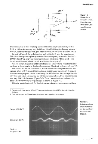
Figure 7-6.
Output waveform
and distortion for
my first oscillator.
Distortion was
0.0025%.
47