
Page 71 - Analog Circuit Design Art, Science, and Personalities
P. 71
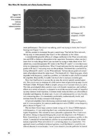
Max Wien, Mr. Hewlett, and a Rainy Sunday Afternoon


                                                                           output 10VDIV


                                                                           Distortion .0015%


                                                                           A2 Output (AC
                                                                          coupled) . 1VDIV

                                                                           Horiz. =
                                                                           200psecDIV

                         more performance. The circuit was talking, and I was trying to listen, but I wasn’t
                         hearing (see Figure 7-14).
                           All this seemed to exonerate the gain control loop. That left the Wien network,
                         the op amp, or some parasitic that wasn’t on the schematic as the villain.
                           I considered the possible effects of voltage coefficient in the Wien network resis-
                         tors and ESR or dielectric absorption in the capacitors. Sometimes when you don’t
                         know how to make things better you can learn by trying to make them worse. So I
                         added tiny, controlled parasitic RC terms to the Wien R’s and C’s to test their sensi-
                         tivity to component imperfections. What I found indicated that the reasonably good
                         grades of R and C I was using were not the problem. I bolstered this conclusion by
                         trying different R’s and C’s in the Wien network. Various decent grades of compo-
                         nents all produced about the same result. That kinda left A1  . Open loop gain, which
                         degrades with frequency, could be a problem, so I decided to add a buffer to unload
                         the amplifier. Beyond this, I couldn’t do much else to increase available gain.
                           Now that I had license to accuse the op amp, the answer quickly seemed appar-
                         ent. This circuit was in violation of a little known tenet of precision op amp circuits:
                         Williams’s Rule. Williams’s Rule is simple: always invert (except when you can’t).
                         This rule, promulgated after countless wars with bizarre, mysterious, and stubborn
                         effects in a variety of circuits, is designed to avoid the mercurial results of imperfect
                         op amp common mode rejection. Common mode-induced  effects are often difficult
                         to predict and diagnose, let alone cure. A zero volt summing point is a very friendly,
                         very reassuring place. It is (nominally) predictable, mathematically docile, and
                         immune from the sneaky common mode dragons.
                           All present amplifiers have decreasing common mode rejection with frequency,
                         and A1 is no exception. Its common mode rejection ratio (CMRR) versus frequency
                         plot is shown in Figure 7-15.
                           The oscillator forces large common mode swings at Al. Since CMRR degrades
                         with frequency, it’s not surprising that I saw somewhat increased distortion at
                         higher frequencies. This seemed at least a plausible explanation. Now I had to test
                         the notion. Doing so required bringing the circuit into alignment with Williams’s
                         Rule. Committing Al’s positive input to ground seems an enormous sacrifice in this
                         circuit. I considered various hideous schemes to accomplish this goal. One abomi-
                         nation coupled the Wien network to A1 ’s remaining input via a transformer. This
                         approach wasn’t confined to technical ugliness; in all likelihood, it would be con-
                         sidered obscene in some locales. I won’t even sketch it, lest the publisher be hauled


         52