
Page 70 - Analog Circuit Design Art, Science, and Personalities
P. 70
Jim Williams
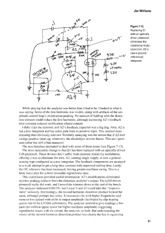
Figure 7-13.
Replacing 01
with an optically
driven photocell
eliminates the
resistance rnodu-
lation trim. A2 is
now a ground-
referenced
Integrator.
While praying that the analyzer was better than it had to be, I looked at what it
was saying. Some of the first harmonic was visible, along with artifacts of the am-
plitude control loop’s rectification peaking. KO amount of fiddling with the distor-
tion trimmer could reduce thc first harmonicl although increasing A2’s fcedback
time constant reduced recti lication rclatcd content.
I didn’t like the trimmer, and A2‘s feedback capacitor was a big dog. Also, A2 is
not a true integrator and has noise gain from its positive input. This sccmed more
irritating than obviously relevant. Similarly annoying was the notion that if A2 ever
swings positive (start-up, whatevcr), the electrolytic reverse biases. This ain’t pei-ti-
nent either but still is bad mariners!
The next itcratiori attempted to deal with some of these issues (see Figure 7- 13).
The most noticeablc change is that QI has been replaced with an optically driven
CdS photocel!. These devices don’t suffer from parasitic resistivity modulation,
offering a way to eliminatc the trim. A2! running single supplyl is now a ground-
sensing type configured as a true integrator. The feedback components are arranged
in it iycak. attempt to get a long time constant with improved settling time. l,astly,
the L X reference has bceri increased. forcing grcater oscillator wing. This is a
brutc force play for a more ravorable signal/noise ratio.
‘This experiment provided uscful information. A2’s modifications eliminated
rectifier peaking artifacts from the distortion analyzcr’s outpui. The LED-driven
photocell really did work, and 1 tosscd the trimmer down to the cnd of the bench.
Thc analyzer indicaLed O.OOlS%? hut I wasn‘t sure if 1 could take this “improvc-
ment” seriously. Interestingly, the second harmonic distortion product looked the
same. although perhaps less noisy. It incrcascd a bit with higher frcquencies and
!nore or less ratiocd with shifts in output amplitude (facilitated by clip-lcading
xross one of !lie l,T!004 rcfcrences). The analyzer sccmed to give readings a few
parts-per-mill ion (ppm) lower for higher oscillator amplitudc, suggesting
ues with the circuit. the analyzer: or both. But understanding thc
source of the second harmonic distortion product was clearly the kcy to squeezing
51