
Page 72 - Analog Circuit Design Art, Science, and Personalities
P. 72
Jim Williams
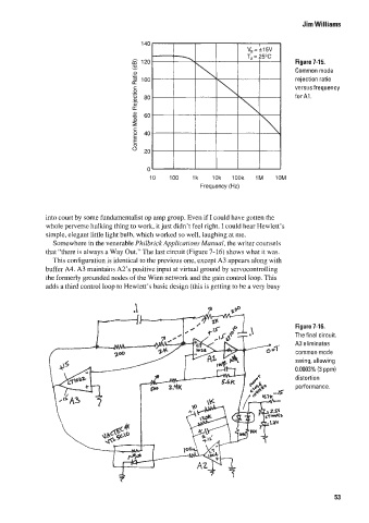
Figure 7-15.
Common mode
rejection ratio
versus frequency
for Al.
into court by some fundamentalist op amp group. Even if I could have gotten the
whole perverse hulking thing to work, it just didn‘t feel right. I could hear Hewlett’s
simple, elegant little light bulb, which wJorked so well, laughing at me.
Somewhere in the venerable Philbr-ick Applicutions Munuul, the writer counsels
that “there is always a Way Out.” The last circuit (Figure 7-16) shows what il was.
This configuration is identical to the previous one, except A3 appears along with
buffer A4. A3 maintains A2’s positive input at virtual ground by servocontrolling
the formerly grounded nodes of the Wien network and the gain control loop. This
adds a third control loop to Hewlett’s basic design (this is getting to be a very busy
Figure 7-16.
The final circuit.
A3 eliminates
common mode
swing, allowing
0.0003% (3 pprni
distortion
performarice.
53