
Page 81 - Analog Circuit Design Art, Science, and Personalities
P. 81
True Analog Circuit Design
Example 2. The Precision Rectifier
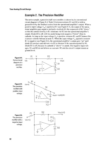
The next example, a precision half-wave rectifier. is shown by its conventional
circuit diagram in Figure 8-4. Node X between resistors R 1 and R2 is held at
ground level by the feedback action from the operational amplifier‘s output. When a
positive input voltage V,, is applied at R I (see Figurc 8-5), the output of the opera-
tional amplifier goes negative and pulls via diode DI the output end ofR2 “down,”
so that the current flowing in R1 continues via R2 into the operational amplifier’s
output. Diode D2 is off. with its anode being more negative (“lower”) than its
cathode. As long as the input voltage Vi,, is positive, resistors R1 and R2 behave like
a seesaw with the fulcrum at node X. When the input voltage V,, applied to resistor
R 1 is negative (see Figure 8-6), the operational amplifier’s output goes “up” until
diode D2 conducts and delivers via D2 to fulcrum X the current required by R1.
-
Diode DI is off, because its cathode is “above” its anode. For negative input volt-
ages, R1 and R2 do not behave as a seesaw: R2 and the circuit’s output remain at
ground level.
Figure 8-4. R1 X R2 0
Conventional Vin Vout
diagram of a D1
precision
rectifier.
D2
Figure 8-5.
The precision
rectifier with A
positive input
voltage.
R1 R2 Vout=O
Figure 8-6. 0
The precision
rectifier with a Vin<O
negative input
voltage. I
D2
I I
62