
Page 100 - Analog and Digital Filter Design
P. 100
97
Poles and Zeroes
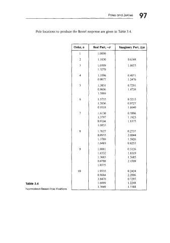
Pole locations to produce the Bessel response are given in Table 3.4.
Order, n Real Part, -0 Imaginary Part, Gjw
1 1 .0000
2 I. 1030 0.6368
3 1.0509 1.0025
1.3270
4 1.3596 0.407 1
0.9877 1.2476
5 1.385 1 0.7201
0.9606 1.4756
1.5069
6 1.5735 0.3213
1.3836 0.9727
0.93 18 1.6640
7 1.6130 0.5896
1.3797 1.1923
0.9104 1.8375
1.6853
8 1.7627 0.2737
0.8955 2.0044
1.3780 1.3926
1.6419 0.8253
9 1.8081 0.5126
1.6532 1.0319
1.3683 1.5685
0.8788 2.1509
1.8575
10 1.9335 0.2424
0.8684 2.2996
1.8478 0.7295
Table 3.4 1.6669 1.2248
1.3649 1.7388
Normalized Bessel Pole Positions