
Page 95 - Analog and Digital Filter Design
P. 95
92 Analog and Digital Filter Design
In the time domain Laplace Transforms give the response for an impulse. The
impulse has a unit area and infinitely narrow width. A far more practical
response is that obtained following the application of a step voltage. A step of
amplitude “a” units-a.u(t)-in the time domain has a function als in the fre-
quency domain, so multiplying the transfer function by 11s (assuming a unit
step) gives the desired result. Using a step input voltage, the frequency domain
response becomes:
a/s (s + b).
a A B
-=- +-
s(s+b) s s+b
By the cover-up rule, A = a/b[s = 01
B = a/-b[s = -b]
a -a/b
So this gives: - and -
bs s+b
This equates to a step of nlb - albe-”‘. Since a and b both equal lICR, the
-I
equation simplifies and the time domain output voltage is, V(l) = 1 - ez.
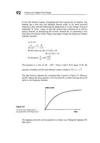
The time domain response for a lowpass filter is given in Figure 3.8. Decreas-
ing RC reduces the decay period in the time domain, as well as raising the cutoff
point in the frequency domain.
AMPLITUDE
Lowpass Filter with Step Input TIME
The highpass network can be analyzed in a similar way. Taking the highpass RC
filter gives: