
Page 92 - Analog and Digital Filter Design
P. 92
Poles and Zeroes 89
pole E). If a is negative the signal will decay with time. The more negative CT
becomes, moving left and away from the imaginary o axis, the faster the signal
decays. If 0 is to the right of the o axis, the amplitude of the signal rises by the
initial step value then grows exponentially.
The imaginaryjo axis describes the oscillatory nature of the signal and is often
called the frequency axis. Moving the pole away from the S-plane origin causes
the oscillation frequency to increase. If a point on the imaginary axis represents
a signal, the amplitude response has a step increase to a level that is then main-
tained forever (as shown by pole B). Actually this signal would be represented
by two points, both with the same value of o, one above the real axis and one
below. A sine wave has both a positive and a negative frequency, which is an
interesting concept.
Complex signals, or responses, can comprise two or more points in the S-plane.
For example a signal that combined a decaying and an oscillatory signal would
be represented by two points, both to the left of the o axis (to give the decay)
and symmetrically above and below the CT axis (to give the oscillation). A filter
response can be described in a similar way. The points described above are called
poles and are represented by crosses in the S-plane. There are also points called
zeroes which often lie on the w axis, and these are represented by small circles
in the S-plane. These describe a zero response, that is, no output, at certain
frequencies. Given a pole-zero diagram it is possible to predict the frequency
response of a circuit.
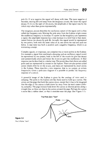
A powerful image of the S-plane is given by the analogy of tents used in
camping. The poles in the S-plane are like those used to hold up a canvas. The
zeroes are like pegs that hold the canvas down, except that it has to be imagined
that the edge of the canvas is held down far away from the tent's center (infin-
ity, actually). The pegs (zeroes) hold down the canvas at discrete points along a
straight line, so there are dips in the canvas around the pegs. Perhaps the canvas
is more like a rubber sheet, so that it stretches near the pegs. (See Figure 3.5.)
The Pole-Zero 'Tent"
Figure 3.5
The S-Plane "Tent"