
Page 93 - Analog and Digital Filter Design
P. 93
90 Analog and Digital Filter Design
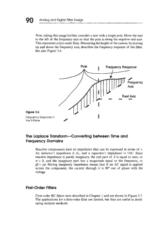
Now, taking this image further, consider a tent with a single pole. Move the tent
to the left of the frequency axis so that the pole is along the negative real axis.
This represents a first-order filter. Measuring the height of the canvas, by moving
up and down the frequency axis, describes the frequency response of the filter.
See also Figure 3.6.
Pole I Frequency Response
I /
Real Axis
-I-
Frequency Response in
the S-Plane 0
The Laplace Transform-Converting between Time and
Frequency Domains
Reactive components have an impedance that can be expressed in terms of s.
An inductor's impedance is sL, and a capacitor's impedance is l/sC. Since
reactive impedance is purely imaginary, the real part of S is equal to zero, or
o = 0, and the imaginary part has a magnitude equal to the frequency, or
jb = jo. Having imaginary impedance means that if an AC signal is applied
across the component, the current through it is 90" out of phase with the
voltage.
First-Order Filters
First-order RC filters were described in Chapter 1 and are shown in Figure 3.7.
The applications for a first-order filter are limited, but they are useful in devel-
oping analysis methods.