
Page 94 - Analog and Digital Filter Design
P. 94
Poles and Zeroes 9 1
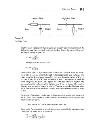
Lowpass Filter Highpass Filter
R C
Figure 3.7
First-Order Filters
The frequency response of these circuits can be easily described in terms of the
S-plane because they are simple potential dividers. Taking the lowpass filter first,
the output voltage is given by:
V" =v, ljSC
R + 1,'sC
multip1.v top and bottom by sC
1
V,=I.:-
1 + sCR
The equation 1/( 1 + sCR) is the transfer function for this filter. Since it is a first-
order filter it only has one pole located on the negative real axis. In fact, a pole
exists when the denominator is equal to zero, and this occurs when sCR = -1.
In other words, S = -1ICR. Now, intuitively, if R or C is decreased in value the
cutoff frequency is raised. This agrees with the pole location negative and
moving along the real axis in the S-plane, away from the origin. The transfer
function also has a zero, located at infinity. This can be explained because when
S = -; the denominator is equal to infinity and therefore the equation is equal
to zero.
The Laplace Transforms can be used to determine the time domain response of
the RC filter. From published tables of time and frequency domain equivalents
(many sources) is given:
Time domain ae-"' = Frequency domain a/(s + b)
The transfer function needs manipulating to make it suitable for transformation.
Letting a = 1/CR and b = 1/CR results in:
VO 1ICR 1
---=- -
V, s+l/CR sCR+1