
Page 91 - Analog and Digital Filter Design
P. 91
88 Analog and Digital Filter Design
If the filter is third-order or higher, finding the pole positions are more difficult.
Fortunately, the pole (and zero) positions of many filter designs have been pub-
lished. There are also equations available for many designs to allow the pole and
zero positions to be calculated.
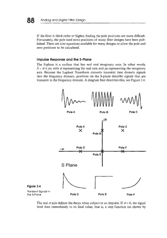
Impulse Response and the S-Plane
The S-plane is a surface that has real and imaginary axes. In other words,
S = o +jo, with o representing the real axis and jo representing the imaginary
axis. Because the Laplace Transform converts transient time domain signals
into the frequency domain, positions on the S-plane describe signals that are
transient in the frequency domain. A diagram best describes this; see Figure 3.4.
Pole A Pole B Pole C
i'
Pole A Pole C
X X
Pole B Pole F
S Plane
Figure 3.4
Transient Signals in
the S-Plane Pole D Pole E Pole F
The real oaxis defines the decay when subject to an impulse. If o= 0, the signal
level rises immediately to its final value; that is, a step function (as shown by