
Page 99 - Analog and Digital Filter Design
P. 99
94 Analog and Digital Filter Design
Bessel Poles
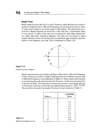
Bessel response poles also lie on a circle. However, when the poles are scaled to
produce a response with a 3 dB cutoff frequency, the circle does not have a radius
of unity and its center is not at the origin of the S-plane. The natural pole posi-
tions for a Bessel response are found for a filter that has a transmission delay
of one second. In other words, they are normalized for their delay characteris-
tics rather than their frequency response. The poles are not placed at equal
angular distances from one another; they are spaced at approximately equal dis-
tances in the imaginary axis only. This is illustrated in Figure 3.10.
I iw
-I
Figure 3.10
Bessel Pole Zero Diagram I
Bessel response poles can be used to produce a filter with a 3 dB cutoff frequency
if their positions are scaled. A table of pole positions for the Bessel response with
a 3 dB cutoff frequency is provided here in Table 3.4. These values were found by
re-normalizing the pole positions given by Thomson, which were normalized for
a one-second delay. The frequency normalization process required the division
of Thomson’s values by a factor that was approximately equal to: 4((2n -1).ln2).
The actual factors used to normalize Thomson’s values are given in Table 3.3.
Normalizing
Order, n Factor
1 1
2 1.36
3 1.75
4 2.13
5 2.42
6 2.7
7 2.95
8 3.17
Table 3.3 9 3.39
10 3.58
Bessel Normalizing Factors