
Page 97 - Analog and Digital Filter Design
P. 97
94 Analog and Digital Filter Design
AMPLITUDE
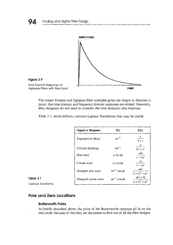
Figure 3.9
Time Domain Response of
Highpass Filters with Step Input TIME
The simple lowpass and highpass filter examples given are simply to illustrate a
point: that time domain and frequency domain responses are related. Generally,
filter designers do not need to consider the time domain's step response.
Table 3.1, which follows, contains Laplace Transforms that may be useful.
a
Exponential decay ae-b'
b+s
a
Critical damping ate-b' (b+s)'
am
Sine wave a.sinwt
S2 +m'
as
Cosine wave a.coswt
S2 +w'
am
Damped sine wave ae-b'. sin ot
(s+ b)' + w2
a(s+b)
Table 3.1 Damped cosine wave ae-b'.cosot
(S+b)] +w'
Laplace Transforms
Pole and Zero locations
Butterworth Poles
As briefly described above, the poles of the Butterworth response all lie on the
unit circle; because of this they are the easiest to find out of all the filter designs.