
Page 228 - Analog and Digital Filter Design
P. 228
Impedance Matching Networks 225
A diplexer can be made from lowpass and highpass filters: one port will output
signals that are below the cutoff frequency, and the other port will output signals
that are above the cutoff frequency. The diplexer will present the correct imped-
ance at its input port at all frequencies, provided that each output port is loaded
with the correct impedance (this is usually 50Q). The load impedance connected
to the output port only needs to be correct at the frequencies in the passband.
Outside the passband, slight changes to the load impedance have little effect on
the diplexer’s input impedance.
In a sinular way, bandpass and bandstop filters can be used to produce a
diplexer. The passband of one filter is the stopband of the other. Provided that
each filter presents high impedance outside its passband, and is terminated cor-
rectly within its passband, the source will see constant load impedance.
The most popular application for a diplexer is the termination of a passive
mixer intermediate frequency port. A mixer has three ports: local oscillator
(LO); radio frequency (RF); and intermediate frequency (IF). Signals at the RF
port are mixed with signals at the LO port. The result is usually a lower
frequency signal out of the IF port that is the difference between RF and LO
frequencies. The mixing process also produces the sum of RF and LO frequen-
cies out of the IF port, and there are other unwanted spurious signals at the IF
post as well. For optimum performance, the mixer IF port must see 50Q at a!I
frequencies.
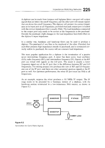
As an example, suppose the mixer produces a 10.7MHz IF output. The IF
stage needs to be preceded by a bandpass section of a diplexer, with the
bandstop section terminated in a low-inductance 50Q resistor, as shown in
Figure 8.2.
MIXER
INPUT
DUMMY LOAD
Figure 8.2
Termination for Out-of-Band Signals