
Page 230 - Analog and Digital Filter Design
P. 230
ImQedance Matching Networks 227
The delta form is more reliable because if one resistor becomes open circuit there
is still a path between all ports. In this case the impedance matching will be
incorrect and the power distribution will be uneven, but the result would not be
catastrophic.
Alternatively, a transformer-coupled power splitter or combiner could be used
to provide impedance matching. These are usually specified for particular fre-
quency bands, because transformers are usually effective over only about two
frequency decades. Isolation between ports is usually at least 30dB with this type
of power splitter. If two sources were being combined, a strong signal from one
source could still reach the output stage of the other source. If this happens,
one signal will mix with the other and the result would be unwanted spurious
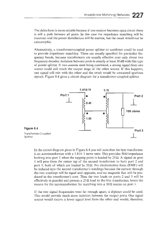
signals. Figure 8.4 gives a circuit diagram for a transformer-coupled splitter.
1.414:lt 1:lt
Figure 8.4
Transformer-Coupled
Splitter
In the circuit diagram given in Figure 8.4 you will note that the first transformer
is an autotransformer with a 1.414: 1 turns ratio. This provides 5OR impedance
looking into port 1 when the tapping point is loaded by 25R. A signal on port
1 will pass from the center tap of the second transformer to both port 2 and
port 3, both of which are loaded by 50R. No electromotive force (EMF) wi!l
be induced into the second transformer’s windings because the current through
the two windings will be equal and opposite, and no magnetic flux will be pro-
duced in the transformer’s core. Thus the two loads on ports 2 and 3 will be
effectively in parallel and present a 25 R load to the first transformer, hence the
reason for the autotransformer for matching into a 50R source on port I.
If the two signal frequencies were far enough apart, a diplexer could be used.
This would provide much more isolation between the output ports. One signal
source would receive a lower signal level from the other and would, therefore,