
Page 234 - Analog and Digital Filter Design
P. 234
23 1
Impedance Matching Networks
Impedance Matching Networks
Impedance matching networks are invariably bandpass designs. They are par-
ticularly valuable at radio frequencies (RF) because even small circuits can
behave like a transmission line. From transmission line theory you may know
that if a line is not terminated in its characteristic impedance, signals are
reflected back towards the source.
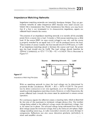
The purpose of an impedance matching network is to transfer all the available
power from a source into a load. Consider a 50Q source matching into a 2OQ
load. If the source EMF (or open circuit voltage) is one volt, and the source
is properly matched by an equal load. 0.5V will be produced across the load.
Thus in terms of power transfer, the load should absorb 0.25/50 watts, or 5mW.
If an impedance-matching circuit is between the source and load, the power
into the load should also be 5mW. The load voltage should therefore be
d(Power x resistance), or d(5.e - 3 x 20) = = 0.3162V. This is illustrated in
Figure 8.7.
Source Matching Network Load
Figure 8.7
Impedance Matching Principles
With no matching network in place the load voltage can be determined by
potential divider calculations: RLI(RL + RS) = 20170 = 0.2857V. The power
lost by direct connection is not very significant, so at low frequencies it is not
usual to provide impedance matching circuits. However, at radio frequencies, the
power reflected back towards the source must be minimized to ensure correct
operation.
For continuous signals the reflection causes a standing wave, which is described
by the ratio of the maxinium to minimum voltages along a line. The incident
voltage being added to the reflected voltage causes the maximum voltage; that
is, the waves are in phase. The reflected voltage being subtracted from the inci-
dent voltage causes the minimum voltage; that is, the waves are anti-phase. High-
voltage standing waves (e.g., in radio transmitter circuits) can cause damage to
components. Reflections can also cause distortion products, particularly in
mixer and amplifier circuits.