
Page 229 - Analog and Digital Filter Design
P. 229
226 Analog and Digital Filter Design
If the mixer is being used for direct conversion, producing a baseband output
(such as audio), the diplexer needs to have lowpass and highpass sections. The
lowpass section precedes the low frequency amplifier or signal processing stage.
The highpass section is terminated in 50Q and provides the correct impedance
for the RF and local oscillator signals.
Power Splitters and Combiners
Suppose you have two high-frequency signals that you wish to transmit over one
signal path. Simply joining the two signal sources together is not good enough
because the output signal at one source could damage the output circuits of the
other source. Also, each source's output level depends on having the correct load
impedance. If the source and load impedance are not matched there will be reflec-
tions that could cause damage to the source in high-power systems. The solution
is to use a power splitter that can be in one of three forms: a resistive network, a
transformer-coupled circuit, or a diplexer. The choice depends on the application.
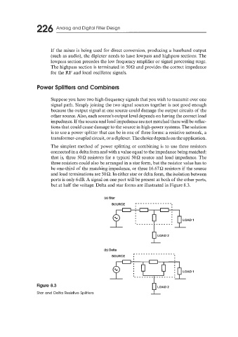
The simplest method of power splitting or combining is to use three resistors
connected in a delta form and with a value equal to the impedance being matched;
that is, three 50Q resistors for a typical 50Q source and load impedance. The
three resistors could also be arranged in a star form, but the resistor value has to
be one-third of the matching impedance, or three 16.67Q resistors if the source
and load terminations are 50Q. In either star or delta form, the isolation between
ports is only 6dB. A signal on one port will be present at both of the other ports,
but at half the voltage. Delta and star forms are illustrated in Figure 8.3.
(a) Star
9
Figure 8.3
LOAD 2
Star and Delta Resistive Splitters I