
Page 238 - Analog and Digital Filter Design
P. 238
Impedance Matching Networks 235
and a negative reactance represents a capacitance. In equations to find
component values, the magnitude of Xis used (otherwise this results in negative
capacitance! ).
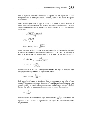
The L matching network of type A, shown in Figure 8.8a, has a reactance in
series with the signal source and a shunt element across the load. The load
impedance to be matched is greater than the source (RL > RS). The reastance
values are:
Jm-RScosP
xl=
sin p
5.
where angle p = tan-' ~ -
The L matching network of type B, shown in Figure 8.8b, has a shunt reactance
across the signal source and an element in series with the load. The load imped-
ance to be matched is less than the source (RL < RS). The reactance values are:
sin p
X1= RS.RL.
RL .cos p - 1/Rs.RL
sin p
X1= RS.RL.
-JRs.RL
In this case, since RL < RS, the equation to find the angle is modified, so it
always gives the square root of a positive number.
RL
In L networks of both type A and type B the component type and value of reac-
tance X# depends on the center frequency of matching and on whether the reac-
tance is positive or negative. Positive reactances are inductors, where X= 2rFcL.
To find the value of inductance L, you simply transpose the equation.
. Transposing this
2nFc C
Similarly, negative reactances are capacitors where X= ~
equation to find the value of capacitance C, transpose this equation and use the
magnitude of A'.