
Page 264 - Analog and Digital Filter Design
P. 264
Phase-Shift Networks (All-Pass Filters) 2
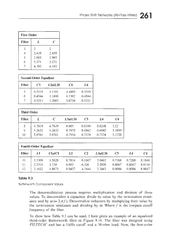
First Order
Third Order
1 Filter I L C L3alL3b C3 L4 c4 1
Fourth-Order Equalizer
Filter 1 L1 Cla/Cl L2 C2 L3alL3b CT L4 c4
2.3308 1.5628 0.7814 0.1667 2.0462 0.7268 0.7268 8.1846
2.2316 1.724 0.862 6.326 2.2039 0.8067 0.8067 8.8154
2.1022 1.8873 0 9437 4.7444 2.2462 0.9086 0.9086 8.9847
Table 9.3
Butteworth Component Values
The denormalization process requires multiplication and division of these
values. To denormalize a capacitor, divide its value by the termination resist-
ance and by w (= 2.nf). Denormalize inductors by multiplying their value by
the termination resistance and dividing by cr). Where f is the lowpass cutoff
frequency of the filter.
To show how Table 9.3 can be used, I have given an example of an equalized
third-order Butterworth filter in Figure 9.14. The filter was designed using
FILTECH’ and has a 1 kHz cutoff and a 50-ohm load. Now. the first-order