
Page 268 - Analog and Digital Filter Design
P. 268
Phase-Shift Networks (All-Pass Filters) 265
rp = 1.0;
ip = 0~0;
for(k = 1: k c= order; ktt)
1
x = (2*k - l)*Pi/(2.0*order);
1 = 0.5 * (gamma + l.O/gamma) cos(x);
r = -0.5 * (gama - l.O.'gamma) * sin(x);
rpt = ip*(i-normalizedfrequencyl - rp*r;
ipt = rp*(normalizedFrequency-il - r*ip;
ip = ipt;
rp = rpt;
I
*magnitude = 20.0 * loglO(hSubZero:sqrtlip*ip + rp*rp) 1:
*phase = 180.0 * atan2: ip, rpl /PI;
recur3 ;
1
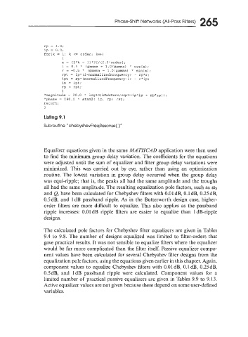
Listing 9.1
Subroutine "chebyshevFreqResonse( 1''
Equalizer equations given in the same MATHCAD application were then used
to find the minimum group delay variation. The coefficients for the equations
were adjusted until the sum of equalizer and filter group delay variations were
minimized. This was carried out by eye, rather than using an optimization
routine. The lowest variation in group delay occurred when the group delay
was equi-ripple; that is, the peaks all had the same amplitude and the troughs
all had the same amplitude. The resulting equalization pole factors, such as mR
and Q, have been calculated for Chebyshev filters with 0.01 dB, 0.1 dB, 0.25d3,
0.5dB, and 1dB passband ripple. As in the Butterworth design case, higher-
order filters are more difficult to equalize. This also applies as the passband
ripple increases: 0.01dB ripple filters are easier to equalize than IdB-ripple
designs.
The calculated pole factors for Chebyshev filter equalizers are given in Tables
9.4 to 9.8. The number of designs equalized was limited to filter-orders that
gave practical results. It was not sensible to equalize filters where the equalizer
would be far more complicated than the filter itself. Passive equalizer compo-
nent values have been calculated for several Chebyshev filter designs from the
equalization pole factors. using the equations given earlier in this chapter. Again.
component values to equalize Chebyshev filters with 0.01 dB, 0. I dB, 0.25dB.
0,5dB, and 1dB passband ripple were calculated. Component values for a
limited number of practical passive equalizers are given in Tables 9.9 to 9.13.
Active equalizer values are not given because these depend on some user-defined
variables.