
Page 263 - Analog and Digital Filter Design
P. 263
260 Analog and Digital Filter Design
to increase the peak delay frequency of the second-order section to maintain
the equi-ripple delay overall.
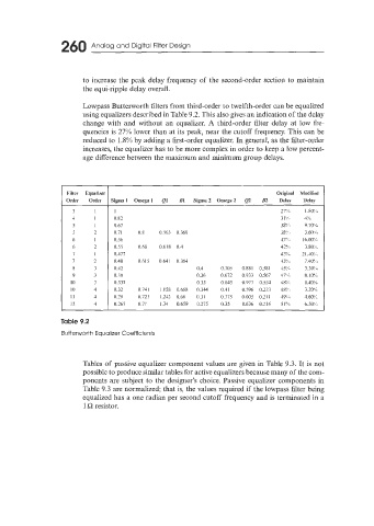
Lowpass Butterworth filters from third-order to twelfth-order can be equalized
using equalizers described in Table 9.2. This also gives an indication of the delay
change with and without an equalizer. A third-order filter delay at low fre-
quencies is 27% lower than at its peak, near the cutoff frequency. This can be
reduced to 1 .X% by adding a first-order equalizer. In general, as the filter-order
increases, the equalizer has to be more complex in order to keep a low percent-
age difference between the maximum and minimum group delays.
Filter Equalizer Original Modified
Order Order Sigma I Omega I Ql B1 Sigma 2 Omega2 Q.2 B2 Delay Delay
3 I 1 27'!,t I .80'!$
4 I 0.82 31'X# 4'7L
5 I 0.67 33':';) 9.70%
5 7 0.71 0.8 0.563 0.369 3S!',, 3.60%,
6 I 0.56 42!,,, I6.00',!h,
6 7 0.55 0.65 0.618 0.4 42% 3.sw
7 I 0.477 43'::) 21.40;;,
7 7 0.48 0.615 0.641 0.3Y4 431!% 7.40!h
8 0.42 0.4 0.705 0.881 0.581 43;4 3.3@!,,,
9 3 0.38 0.36 0.672 0.933 0.567 47% 8.10':b
10 0.335 0.33 0.645 0.977 0.554 4X'X S.40'!?b
I0 4 0.32 0.741 1.155 0.668 0,344 0.41 0.596 0.223 4%" 3.20'!L
II 4 0.29 0.721 1.243 0.66 0.31 0.375 0.605 0.21 I 491,;) 4.60':1,
12 4 0.265 0.71 1.34 0.659 0.275 0.35 0.636 0.216 51% 6.50'::,
Table 9.2
Butterworth Equalizer Coefficients
Tables of passive equalizer component values are given in Table 9.3. It is not
possible to produce similar tables for active equalizers because many of the com-
ponents are subject to the designer's choice. Passive equalizer components in
Table 9.3 are normalized; that is, the values required if the lowpass filter being
equalized has a one radian per second cutoff frequency and is terminated in a
1 Q resistor.