
Page 258 - Analog and Digital Filter Design
P. 258
Phase-Shift Networks (All-Pass Filters) 255
at the input to the first stage. The formulae for calculating component values
are different from those given in Figure 9.11.
R
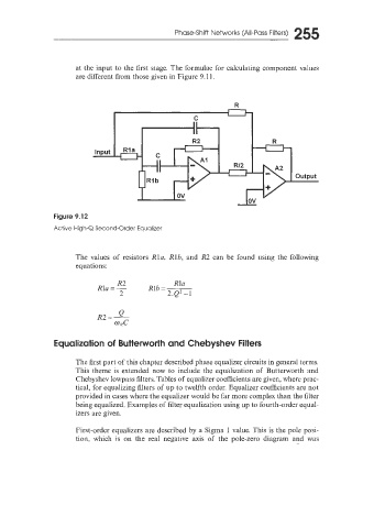
Figure 9.12
Active High-Q Second-Order Equalizer
The values of resistors Rla, Rlb, and R2 can be found using the following
equations:
R2 Rla
Rla = - Rib=-
- 2.Q2-1
3
Equalization of Butterworth and Chebyshev Filters
The first part of this chapter described phase equalizer circuits in general terms.
This theme is extended now to include the equalization of Butterworth and
Chebyshev lowpass filters. Tables of equalizer coefficients are given, where prac-
tical, for equalizing filters of up to twelfth order. Equalizer coefficients are not
provided in cases where the equalizer would be far more complex than the filter
being equalized. Examples of filter equalization using up to fourth-order equal-
izers are given.
First-order equalizers are described by a Sigma 1 value. This is the pole posi-
tion, which is on the real negative axis of the pole-zero diagram and was