
Page 254 - Analog and Digital Filter Design
P. 254
Phase-Shift Networks (All-Pass Filters) 25
shift at this point. The total phase shift of a second-order section, over a 1i7ide
frequency range, is 360O-twice that of a first-order section.
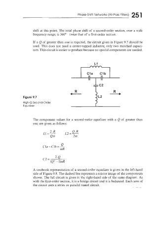
If a Q of greater than one is required, the circuit given in Figure 9.7 should be
used. This does not need a center-tapped inductor, only two matched capaci-
tors. This circuit is easier to produce because no special components are needed.
R R
t ---b
Figure 9.7
High-Q Second-Order
Equalizer
The component values for a second-order equalizer with a Q of greater than
one are given as follows:
2.R Q.R
L1=- L2=-
Q0 20
0
Cln = Clb = =
COR
2.Q
c2 =
(Q2 - l)wR
A textbook representation of a second-order equalizer is given in the left-hand
side of Figure 9.8. The dashed line represents a mirror image of the components
shown. The full circuit is given in the right-hand side of the same diagram. As
with the first-order section, it is a bridge circuit and it is balanced. Each arm of
the circuit uses a series or parallel tuned circuit.