
Page 257 - Analog and Digital Filter Design
P. 257
254 Analog and Digital Filter Design
of the filter being equalized. In the case of quadrature networks, which are
described in this chapter, it is scaled by the passband center frequency.
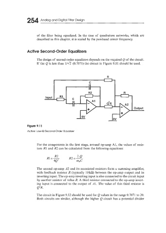
Active Second-Order Equalizers
The design of second-order equalizers depends on the required Q of the circuit.
If the Q is less than 11a (0.7071) the circuit in Figure 9.1 1 should be used.
R
For the components in the first stage, around op-amp Al, the values of resis-
tors R1 and R2 can be calculated from the following equations:
The second op-amp A2 and its associated resistors form a summing amplifier,
with feedback resistor R (typically 10kQ) between the op-amp output and its
inverting input. The op-amp inverting input is also connected to the circuit input
by another resistor of value R. A third resistor connected to the op-amp invert-
ing input is connected to the output of Al. The value of this third resistor is
e'R.
The circuit in Figure 9.12 should be used for Q values in the range 0.7071 to 20.
Both circuits are similar, although the higher Q circuit has a potential divider