
Page 252 - Analog and Digital Filter Design
P. 252
Phase-Shift Networks (Ail-Pass Filters) 249
Figure 9.4
Schematic Symbol of
First-Order Equalizer c.,----..--..--
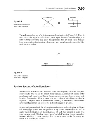
The pole-zero diagram of a first-order equalizer is given in Figure 9.5. There is
one pole on the negative real axis and, at an equal distance from the origin, one
zero on the positive real axis. Since both pole and zero are at an equal distance
from any point on the imaginary frequency axis, signals pass through the filter
without attenuation.
Pole Zero
____Q_.
Figure 9.5
First-Order Equalizer
Pole-Zero Diagram
Passive Second-Order Equatizers
Second-order equalizers can be tuned to set the frequency at which the peak
delay occurs. This makes the circuit more versatile. A cascade of second-order
equalizers. each tuned to a different frequency, can provide a delay across a wide
band of frequencies. What is more, the peak value of the delay can also be
adjusted. The peak value is proportional to the Q of the circuit, and different
circuit configurations are needed for different ranges of Q value.
A practical passive circuit for a low-Q second-order equalizer is given in Figure
9.6. This design can be used for Q values of up to one. In the equations for the
center-tapped inductor, L3, the inductance of each half section is given. The
total inductance of L3 is four times that of each half section, since the coupling
between windings is close to unity. The circuit is tuned to the frequency mR,
which is in radians per second.