
Page 256 - Analog and Digital Filter Design
P. 256
Phase-Shift Networks (All-Pass Filters) 25
The amplitude of signals passing through the second-order equalizer do not
change with frequency. This is because the poles and the zeroes are placed ai
equal and opposite positions from all points on the frequency axis. The fre-
quency at which the group delay peaks is dependent both on Alpha and Beta
coordinates. With the poles and zeroes close to the real axis the peak delay
occurs at low frequencies. Conversely, as the poles and zeroes move away from
the real axis the peak delay occurs at higher frequencies. The closer the poles
and zeroes are to the imaginary axis. the greater the peak delay amplitude.
Active First-Order Equalizers
Active equalizer sections use component values that are dependent on both
the pole and zero positions and on the designer’s choice. Ths is the opposite
of passive equalizers that do not allow the designer any scope in the design,
because the component values depend only on the impedance and the pole and
zero locations.
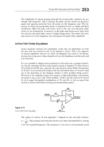
It is not possible to design active equalizers in the same way as passive equaliz-
ers. See, for example, the first-order equalizer given in Figure 9.10. The resistors
R1 and R2 set the DC gain, typically they may both be about 10 kQ. The product
of R and Cis set by the pole location; but the individual values of R and C used
are at the discretion of the designer, subject to their product being correct.
However, if the amplifier’s input bias current is high (particularly with bipolar
op-amps) it may cause a DC offset problem. In this case the value of R should
be set to equal the parallel combination of R1 and R2, so that an equal bias
current is drawn from both inverting and noninverting inputs.
R2
-
Output
Figure 9.10
Active First-Order Equalizer
The values of resistor R and capacitor C depend on the real pole location:
= -. z This assumes that the pole location has been denormalized by scaling
RC
it for the required frequency. The frequency is the same as the passband cutoff