
Page 253 - Analog and Digital Filter Design
P. 253
250 Analog and Digital Filter Design
e
t ic4 -
L3b
e
L3a
R
R
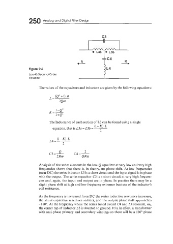
Figure 9.6 IL4
Low-Q Second-Order
Equalizer
The values of the capacitors and inductors are given by the following equations:
(e2 + 1). R
L=
2Qo
1-Q'
K=-
l+Q'
The Inductance of each section of L3 can be found using a single
(l+K).L
equation, that is L3a = L3b =
2
(1-K).L
L4 =
2
Q 2
c3=- c4=-
2Ro QRo
Analysis of the series elements in the low-Q equalizer at very low and very high
frequencies shows that there is, in theory, no phase shift. At low frequencies
(near DC) the series inductor L3 is a short circuit and the input signal is in phase
with the output. The series capacitor C3 is a short circuit at very high frequen-
cies and, again, the input and output are in phase. In practice there may be a
slight phase shift at high and low frequency extremes because of the inductor's
coil resistance.
As the frequency is increased from DC the series inductive reactance increases,
the shunt capacitive reactance reduces, and the output phase shift approaches
-180". At the frequency where the series tuned circuit C4 and L4 resonate, uR,
the center tap of inductor L3 is shunted to ground. It is, in effect, a transformer
with anti-phase primary and secondary windings so there will be a 180" phase