
Page 255 - Analog and Digital Filter Design
P. 255
252 Analog and Digital Filter Design
Figure 9.8 /
/
Schematic and Full Circuit
of Second-Order Equalizer
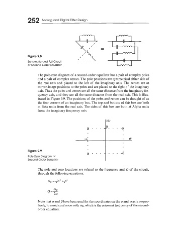
The pole-zero diagram of a second-order equalizer has a pair of complex poles
and a pair of complex zeroes. The pole positions are symmetrical either side of
the real axis and placed to the left of the imaginary axis. The zeroes are at
mirror-image positions to the poles and are placed to the right of the imaginary
axis. Thus the poles and zeroes are all the same distance from the imaginary fre-
quency axis, and they are all the same distance from the real axis. This is illus-
trated in Figure 9.9. The positions of the poles and zeroes can be thought of as
the four corners of an imaginary box. The top and bottom of this box are both
at Beta units from the real axis. The sides of this box are both at Alpha units
from the imaginary frequency axis.
Figure 9.9
- -0
Pole-Zero Diagram of
Second-Order Equalizer
The pole and zero locations are related to the frequency and Q of the circuit,
through the following equations:
WR = j m
Q=- WR
2a
Note that a and p have been used for the coordinates on the oand o axis, respec-
tively, to avoid confusion with wR, which is the resonant frequency of the second-
order equalizer.