
Page 368 - Analog and Digital Filter Design
P. 368
Introduction to Digital Filters 365
ing to the next input, the first output address is the input address plus one (unless
we are at the end of the memory space). All we have to do is continuously incre-
ment the output pointer, remembering to loop back to the bottom of the address
range once we have read from the highest address, and multiply the value stored
in that address by the appropriate coefficient. All the coefficient multiplication
operations have to be carried out before the next input saniple is stored.
Introduction to the Infinite Response Filter
The infinite response filter (IIR) uses a feedback loop, so the output at one clock
period somehow affects the output during the next period. This will have some
sort of exponential effect, so that each output has a smaller effect on the next
output (otherwise the output would be unstable, if you think about it).
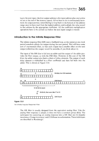
The input of the IIR filter is fed into an adder and the output of the adder pro-
vides the filter output, as with the FIR filter. However, in the case of the IIR
filter, the adder output also feeds a chain of delay elements. The output of each
delay element is multiplied by a filter coefficient and then fed back into the
adder. This is shown in Figure 15.8.
It
32 30 Q30 Result 1
-I-
16 bit (Ql5) result
Shift left, then save bits 17 to 32
16 1
Q15 Result
Figure 15.8
An Infinite Impulse Response Filter
The IIR filter is usually designed from the equivalent analog filter. Like the
analog filter response it adopts, it does not have a constant group delay. The
techniques for converting an analog response into a IIR filter are (1) impulse
invariance; (2) step invariance; and (3) bilinear transformation. These techniques
are described in Rorabaugh.'