
Page 366 - Analog and Digital Filter Design
P. 366
Introduction to Digital Filters 363
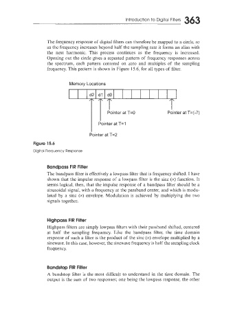
The frequency response of digital filters can therefore be mapped to a circle, so
as the frequency increases beyond half the sampling rate it forms an alias with
the next harmonic. This process continues as the frequency is increased.
Opening out the circle gives a repeated pattern of frequency responses across
the spectrum, each pattern centered on zero and multiples of the sampling
frequency. This pattern is shown in Figure 15.6, for all types of filter.
Memory Locations
Pointer at T=2
Figure 15.6
Digital Frequency Response
Bandpass FIR Filter
The bandpass filter is effectively a lowpass filter that is frequency shifted. I have
shown that the impulse response of a lowpass filter is the sinc (x) function. It
seems logical, then, that the impulse response of a bandpass filter should be a
sinusoidal signal, with a frequency at the passband center, and which is modu-
lated by a sinc (x) envelope. Modulation is achieved by multiplying the two
signals together.
Highpass FIR Filter
ighpass filters are simply lowpass filters with their passband shifted, centered
at half the sampling frequency. Like the bandpass filter, the time domain
response of such a filter is the product of the sinc (x) envelope multiplied by a
sinewave. In this case, however, the sinewave frequency is half the sampling clock
frequency.
Bandstop FIR Filter
A bandstop filter is the most difficult to understand in the time domain. The
output is the sum of two responses; one being the lowpass response, the other