
Page 364 - Analog and Digital Filter Design
P. 364
Introduction to Digital Filters
If the folded FIR filter is implemented in a digital signal processor (DSP). it
requires far less computational effort than the linear FIR filter. Summing cir-
cuits use little processor time, but multiplication requires a number of shift and
add operations. Also, reading the filter coefficients from memory takes time. The
processor is only required to read half the coefficients in a folded FIR filter,
One advantage of the FIR filter, in either form, is that its output is linear phase.
It is linear phase because each input signal passes through all the delay elements,
so a slowly changing signal goes through the same processes as a rapidly chang-
ing signal; all frequencies are delayed equally. In other words the group delay is
constant and is proportional to the number of delay elements in .the filter.
Truncation (Applied to FIR Filters)
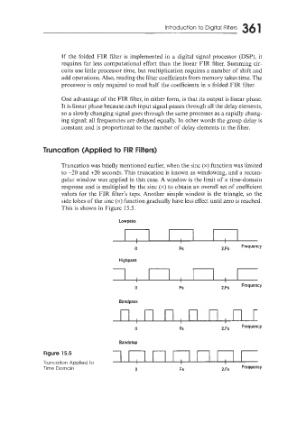
Truncation was briefly mentioned earlier, when the sinc (x) function was limited
to -30 and +20 seconds. This truncation is known as windowing, and a rectan-
gular window was applied in this case. A window is the limit of a time-domain
response and is multiplied by the sinc (x) to obtain an overall set of coefficient
values for the FIR filter’s taps. Another simple window is the triangle, so the
side lobes of the sinc (x) function gradually have less effect until zero is reached.
This is shown in Figure 15.5.
Lowpass
Highpass
0 Fs
Bandpass
Bandstop
Figure 15.5
Truncation Applied to
Time Domain 0 Fs