
Page 101 - Analysis and Design of Machine Elements
P. 101
Detachable Joints and Fastening Methods
3. Determine the load each bolt subjected to according to the bolted joint type (ordinary 79
or precision bolted joints), assembly condition (with preload or without preload) and
loading condition (transverse or axial loading, static or dynamic loading). The basic
approach is first to determine the forces that act on each bolt by each applied load
separately. Then, superpose the forces vectorially to identify the bolt that carries the
greatest load in the group.
4. Determine the critical section dimension, usually the minor diameter d , according
1
to the design criteria.
5. Decide the size of bolts, nuts, washers and so on according to design handbooks and
manufacturers’ catalogues.
3.6.5 Structural Design
Structural design determines bolt layout pattern and bolt number, following these guide-
lines:
1. The bolt layout is usually designed as a simple, symmetric geometry, such as a square,
rectangle or circle.
2. Select an even number of bolts in a group to facilitate manufacture and to ensure
equal loading. Each bolt should have the same size (both diameter and length), thread
series (coarse or fine), material and property class.
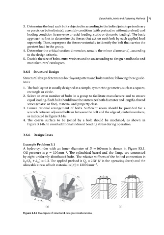
3. Ensure rational arrangement of bolts. Sufficient room should be provided for a
wrench between adjacent bolts or between the bolt and the edge of jointed members,
as indicated in Figure 3.14a.
4. The coarse surface to be joined by a bolt should be machined, as shown in
Figure 3.14b, to avoid additional induced bending stress during operation.
3.6.6 Design Cases
Example Problem 3.1
A hydro-cylinder with an inner diameter of D = 160 mm is shown in Figure E3.1.
−2
Oil pressure is p = 1Nmm . The cylindrical barrel and the flange are connected
by eight uniformly distributed bolts. The relative stiffness of the bolted connection is
k /(k + k ) = 0.3. The applied preload is Q = 2.5F (F is the operating force) and the
m
p
b
b
−2
allowablestressofboltmaterialis[ ] = 120 N mm .
60˚
60˚
30˚ 30˚
M
A
A E M
(a) (b)
Figure 3.14 Examples of structural design considerations.