
Page 102 - Analysis and Design of Machine Elements
P. 102
Analysis and Design of Machine Elements
80
Decide:
(1) The total tensile load carried by each bolt;
(2) The resultant load on the clamped members;
(3) The minor diameter required for the bolts.
p
D
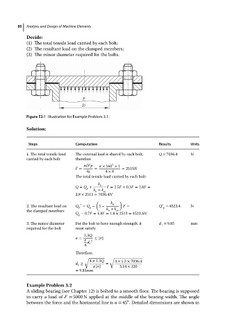
Figure E3.1 Illustration for Example Problem 3.1.
Solution:
Steps Computation Results Units
1. The total tensile load The external load is shared by each bolt, Q = 7036.4 N
carried by each bolt therefore
D p × 160 × 1
2
2
F = = = 2513N
4z 4 × 8
The total tensile load carried by each bolt:
k
Q = Q + b F = 2.5F + 0.3F = 2.8F =
p k + k
b m
2.8 × 2513 = 7036.4N
( k )
′
2. The resultant load on Q P ′ = Q − 1 − b F = Q = 4523.4 N
p
p
the clamped members k + k m
b
Q − 0.7F = 1.8F = 1.8 × 2513 = 4523.4N
p
3. The minor diameter For the bolt to have enough strength, it d = 9.85 mm
1
required for the bolt must satisfy
1.3Q
= ≤ [ ]
2
d
4 1
Therefore,
√ √
4 × 1.3Q 4 × 1.3 × 7036.4
d ≥ =
1 [ ] 3.14 × 120
= 9.85mm
Example Problem 3.2
A sliding bearing (see Chapter 12) is bolted to a smooth floor. The bearing is supposed
to carry a load of F = 5000 N applied at the middle of the bearing width. The angle
∘
between the force and the horizontal line is = 45 . Detailed dimensions are shown in