
Page 103 - Analysis and Design of Machine Elements
P. 103
Detachable Joints and Fastening Methods
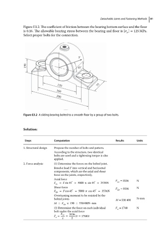
Figure E3.2. The coefficient of friction between the bearing bottom surface and the floor 81
is 0.16. The allowable bearing stress between the bearing and floor is [ ] = 125 MPa.
p
Select proper bolts for the connection.
F
150 45˚
75
120
160
200
Figure E3.2 A sliding bearing bolted to a smooth floor by a group of two bolts.
Solution:
Steps Computation Results Units
1. Structural design Propose the number of bolts and pattern.
According to the structure, two identical
bolts are used and a tightening torque is also
applied.
2. Force analysis (1) Determine the forces on the bolted joint.
Resolve load F into vertical and horizontal
components, which are the axial and shear
force on the joints, respectively.
Axial force
∘ ∘ F Σv = 3536 N
F Σv = F sin 45 = 5000 × sin 45 = 3536N
Shear force F = 3536 N
∘
∘
F Σh = F cos 45 = 5000 × cos 45 = 3536N Σh
Overturning moment to be resisted by the
bolted joints N⋅mm
M = 530 400
M = F Σh × 150 = 530400N • mm
(2) Determine the force on each individual F = 1768 N
a
bolt under the axial force
F 3536
F = Σv = N = 1768N
a
z 2