Page 139 - Analysis and Design of Machine Elements
P. 139

Permanent Connections
                          2  Two identical low carbon steel plates with a thickness of t = 10 mm and width of  117
                             l = 180 mm are going to be joined by the welding process, as shown in Figure P5.4.
                             Both butt joint and lap joint are proposed. The allowable tensile stress of the weld is
                             [  ] = 200 MPa and the allowable shear stress is [  ] = 150 MPa. Decide the maximum
                             load F each of joint can carry.

                                                                                    Lap joint
                                         Butt joint
                                 t                                t
                                                                                          t
                          F                             F    F
                                                                                               F
                                         (a)                                  (b)

                          Figure P5.4 Illustration for Calculation Question 2.


                          Design Problems

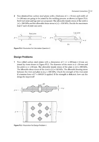
                          1  Two rolled carbon steel plates with a dimension of l × t = 200 mm × 12 mm are
                             joined by rivets shown in Figure P5.5. The diameter of the rivets is d = 20 mm and
                             the pitch is w = 60 mm. The allowable tensile stress of the plate is [  ] = 200 MPa.
                             The allowable shear stress of the rivet is [  ] = 150 MPa. The allowable bearing stress

                             between the rivet and plate is [   ] = 300 MPa. Check the strength of the rivet joint
                                                        p
                             if a tension force of F = 300 kN is applied. If the strength is deficient, how can the
                             design be improved?


                                                      ϕd

                                                                          F
                                                                     t
                          F      t


                           F         l                       w         F


                          Figure P5.5 Illustration for Design Problem 1.
   134   135   136   137   138   139   140   141   142   143   144