
Page 134 - Analysis and Design of Machine Elements
P. 134
Analysis and Design of Machine Elements
112
F
t 1 45°
m
O
k F
t 2
Figure 5.4 Forces on a fillet weld.
The allowable stress of weld relates to the weld material, parent material and welding
processes. If the allowable stress of parent material is [ ], for a weld seam, the allowable
tensile stress can be selected as approximately (0.9–1)[ ]; the allowable compressive
stress [ ] and the allowable shear stress (0.5–0.65)[ ][5].
These calculations neglect weld induced residual stresses, which may sometimes have
adverse effects on the strength of weldments. Although not rigorously correct, these
convenient procedures are considered to be justified for estimation. Detailed stress and
strength calculation for butt and fillet welds subjected to torsional, bending or fatigue
loading, as well as strength analyses for other weld configurations can be referred to in
relevant design handbooks [5].
5.2.4 Design of Welded Joints
The design of welded joints requires consideration of the loads carried by welded joints,
the types of weld materials and parent materials and joint geometries. Welded joint
design usually follows the following procedure and guidelines:
1) Propose welded joint geometry and design the members to be joined;
2) Select parent and weld materials and decide their allowable stresses;
3) Determine the magnitude and the direction of force on the weld under each load,
combine the forces vectorially at the point of weld where the force appears to be
maximum;
4) Analyse stresses the weld is subjected to and compare them with the allowable
stresses of materials to determine the required dimensions.
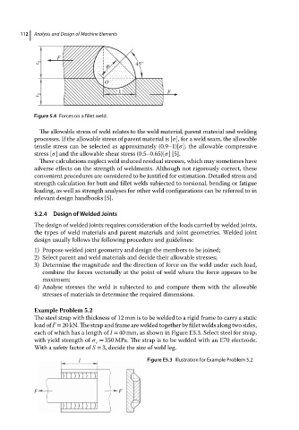
Example Problem 5.2
The steel strap with thickness of 12 mm is to be welded to a rigid frame to carry a static
load of F = 20 kN. The strap and frame are welded together by fillet welds along two sides,
each of which has a length of l = 40 mm, as shown in Figure E5.3. Select steel for strap,
with yield strength of = 350 MPa. The strap is to be welded with an E70 electrode.
s
With a safety factor of S = 3, decide the size of weld leg.
l Figure E5.3 Illustration for Example Problem 5.2.
F F