
Page 133 - Analysis and Design of Machine Elements
P. 133
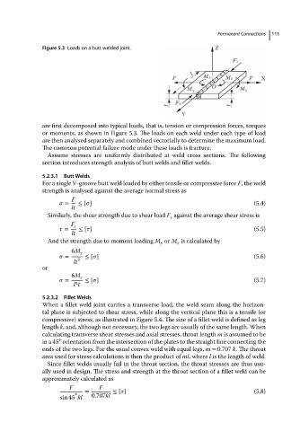
Figure 5.3 Loads on a butt welded joint.                Permanent Connections  111


                          are first decomposed into typical loads, that is, tension or compression forces, torques
                          or moments, as shown in Figure 5.3. The loads on each weld under each type of load
                          are then analysed separately and combined vectorially to determine the maximum load.
                          The common potential failure mode under these loads is fracture.
                            Assume stresses are uniformly distributed at weld cross sections. The following
                          section introduces strength analysis of butt welds and fillet welds.
                          5.2.3.1  Butt Welds
                          For a single V-groove butt weld loaded by either tensile or compressive force F, the weld
                          strength is analysed against the average normal stress as
                                   F
                                  =  ≤ [  ]                                                   (5.4)
                                   lt
                            Similarly, the shear strength due to shear load F against the average shear stress is
                                                                   s
                                   F s
                                  =   ≤ [  ]                                                  (5.5)
                                   lt
                            And the strength due to moment loading M or M is calculated by
                                                                y    z
                                   6M y
                                  =  2  ≤ [  ]                                                (5.6)
                                    lt
                          or
                                   6M z
                                  =     ≤ [  ]                                                (5.7)
                                     2
                                    l t
                          5.2.3.2  Fillet Welds
                          When a fillet weld joint carries a transverse load, the weld seam along the horizon-
                          tal plane is subjected to shear stress, while along the vertical plane this is a tensile (or
                          compressive) stress, as illustrated in Figure 5.4. The size of a fillet weld is defined as leg
                          length k, and, although not necessary, the two legs are usually of the same length. When
                          calculating transverse shear stresses and axial stresses, throat length m is assumed to be
                               ∘
                          in a 45 orientation from the intersection of the plates to the straight line connecting the
                          ends of the two legs. For the usual convex weld with equal legs, m = 0.707 k.Thethroat
                          area used for stress calculations is then the product of ml,where l is the length of weld.
                            Since fillet welds usually fail in the throat section, the throat stresses are thus usu-
                          ally used in design. The stress and strength at the throat section of a fillet weld can be
                          approximately calculated as
                                   F        F
                                    ∘   =        ≤ [  ]                                       (5.8)
                                sin 45 kl  0.707kl