
Page 129 - Analysis and Design of Machine Elements
P. 129
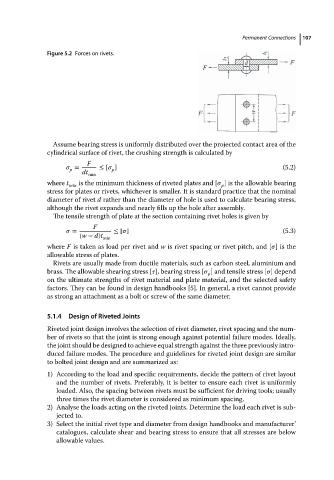
Figure 5.2 Forces on rivets.                            Permanent Connections  107


                            Assume bearing stress is uniformly distributed over the projected contact area of the
                          cylindrical surface of rivet, the crushing strength is calculated by
                                     F
                                  =      ≤ [   ]                                              (5.2)
                                             p
                                p
                                    dt min
                          where t  is the minimum thickness of riveted plates and [   ] is the allowable bearing
                                min                                         p
                          stress for plates or rivets, whichever is smaller. It is standard practice that the nominal
                          diameter of rivet d rather than the diameter of hole is used to calculate bearing stress,
                          although the rivet expands and nearly fills up the hole after assembly.
                            The tensile strength of plate at the section containing rivet holes is given by
                                       F
                                  =          ≤ [  ]                                           (5.3)
                                   (w − d)t min
                          where F is takenasloadper rivetand w is rivet spacing or rivet pitch, and [  ]isthe
                          allowable stress of plates.
                            Rivets are usually made from ductile materials, such as carbon steel, aluminium and
                          brass. The allowable shearing stress [  ], bearing stress [   ] and tensile stress [  ] depend
                                                                        p
                          on the ultimate strengths of rivet material and plate material, and the selected safety
                          factors. They can be found in design handbooks [5]. In general, a rivet cannot provide
                          as strong an attachment as a bolt or screw of the same diameter.


                          5.1.4  Design of Riveted Joints
                          Riveted joint design involves the selection of rivet diameter, rivet spacing and the num-
                          ber of rivets so that the joint is strong enough against potential failure modes. Ideally,
                          the joint should be designed to achieve equal strength against the three previously intro-
                          duced failure modes. The procedure and guidelines for riveted joint design are similar
                          to bolted joint design and are summarized as:
                          1) According to the load and specific requirements, decide the pattern of rivet layout
                             and the number of rivets. Preferably, it is better to ensure each rivet is uniformly
                             loaded. Also, the spacing between rivets must be sufficient for driving tools; usually
                             three times the rivet diameter is considered as minimum spacing.
                          2) Analyse the loads acting on the riveted joints. Determine the load each rivet is sub-
                             jected to.
                          3) Select the initial rivet type and diameter from design handbooks and manufacturer’
                             catalogues, calculate shear and bearing stress to ensure that all stresses are below
                             allowable values.