
Page 128 - Analysis and Design of Machine Elements
P. 128
Analysis and Design of Machine Elements
106
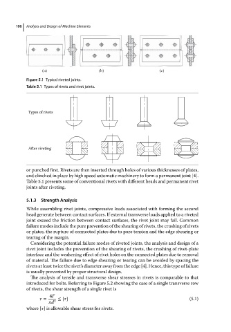
(a) (b) (c)
Figure 5.1 Typical riveted joints.
Table 5.1 Types of rivets and rivet joints.
Types of rivets
After riveting
or punched first. Rivets are then inserted through holes of various thicknesses of plates,
and clinched in place by high speed automatic machinery to form a permanent joint [4].
Table 5.1 presents some of conventional rivets with different heads and permanent rivet
joints after riveting.
5.1.3 Strength Analysis
While assembling rivet joints, compressive loads associated with forming the second
head generate between contact surfaces. If external transverse loads applied to a riveted
joint exceed the friction between contact surfaces, the rivet joint may fail. Common
failure modes include the pure prevention of the shearing of rivets, the crushing of rivets
or plates, the rupture of connected plates due to pure tension and the edge shearing or
tearing of the margin.
Considering the potential failure modes of riveted joints, the analysis and design of a
rivet joint includes the prevention of the shearing of rivets, the crushing of rivet-plate
interface and the weakening effect of rivet holes on the connected plates due to removal
of material. The failure due to edge shearing or tearing can be avoided by spacing the
rivets at least twice the rivet’s diameter away from the edge [4]. Hence, this type of failure
is usually prevented by proper structural design.
The analysis of tensile and transverse shear stresses in rivets is comparable to that
introduced for bolts. Referring to Figure 5.2 showing the case of a single transverse row
of rivets, the shear strength of a single rivet is
4F
= ≤ [ ] (5.1)
d 2
where [ ] is allowable shear stress for rivets.