
Page 130 - Analysis and Design of Machine Elements
P. 130
Analysis and Design of Machine Elements
108
Example Problem 5.1
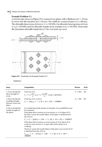
A riveted joint shown in Figure E5.1 connects two plates with a thickness of t = 10 mm
by rivets with the diameter of d = 20 mm. The width the connected plate is l = 180 mm.
The allowable shear stress of rivets is [ ] = 120 MPa, theallowablebearing stress of rivets
is [ ] = 250 MPa and the allowable tensile stress of plates is [ ] = 150 MPa. Determine
p
themaximum allowabletensileforce F the rivet joint can carry.
ϕd
F
t
F t
F l w F
Figure E5.1 Illustration for Example Problem 5.1.
Solution:
Steps Computation Results Units
1. Force decided by From Eq. (5.1), F = 264 kN
1
shear strength of F = 7 × d 2 [ ]= 7 × × 20 2 × 120 = 263760 N
rivets 1 4 4
2. Force decided by From Eq. (5.2), we have F = 350 kN
2
crushing strength F =7dt[ ] = 7 × 20 × 10 × 250 = 350000 N
between rivets and 2 p
plates
3. Force decided by In considering tensile stresses in the plate, two possibilities must
tensile strength of be examined.
the plates If theplate failsintension at crosssection A–A in Figure E5.2,
the force causes the tensile failure of the plate is obtained from
Eq. (5.3) as
F =(l −2d)t[ ] = (180 − 2 × 20) × 10 × 150 = 210000 N
3
If theplate failsintension at crosssection B−B in Figure E5.2,
rivets on cross section A−A must either fail in shear or in
crushing.
The force causes the tensile failure of the plate cross section B−B
is obtained from Eq. (5.3) as
F =(l −3d) t[ ] = (180 − 3 × 20) × 10 × 150 =
tension
180000N