
Page 221 - Analysis and Design of Machine Elements
P. 221
Gear Drives
6) The relationship between the number of virtual spur gear teeth z and the number of 199
v
straight bevel gear teeth z
From d = m z and Eq. (8.67), we have
v m v
z
z = (8.71)
v
cos
7) The virtual spur gear ratio u v
z v2 z cos 1
2
u = = = u 2 (8.72)
v
z v1 z cos 2
1
8.5.2 Forces on Straight Bevel Gear Teeth
Since bevel gear teeth are tapped in both tooth thickness and height, the load applied
on the bevel gear is nonuniform, proportionately greater at the large end. To simplify
calculation, the normal force F is usually assumed to be acting at the midpoint of face
n
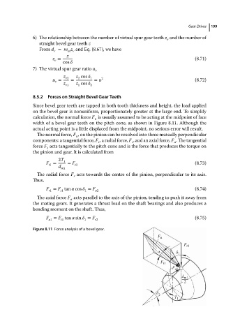
width of a bevel gear teeth on the pitch cone, as shown in Figure 8.11. Although the
actual acting point is a little displaced from the midpoint, no serious error will result.
The normal force, F , on the pinion can be resolved into three mutually perpendicular
n
components: a tangential force, F , a radial force, F ,and an axialforce, F .Thetangential
t r a
force F acts tangentially to the pitch cone and is the force that produces the torque on
t
the pinion and gear. It is calculated from
2T 1
F = = F t2 (8.73)
t1
d
m1
The radial force F acts towards the centre of the pinion, perpendicular to its axis.
r
Thus,
F = F tan cos = F (8.74)
r1 t1 1 a2
The axial force F acts parallel to the axis of the pinion, tending to push it away from
a
the mating gears. It generates a thrust load on the shaft bearings and also produces a
bending moment on the shaft. Thus,
F = F tan sin = F (8.75)
a1 t1 1 r2
Figure 8.11 Force analysis of a bevel gear.
F n
F r1
α δ 1
F t1
F a1
d m1
2
δ 1
T 1