
Page 223 - Analysis and Design of Machine Elements
P. 223
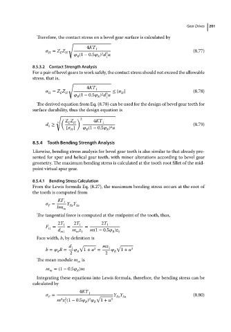
Therefore, the contact stress on a bevel gear surface is calculated by  Gear Drives  201
                                         √
                                                 4KT 1
                                  = Z Z H                                                    (8.77)
                                     E
                                H
                                                       2 3
                                              (1 − 0.5   ) d u
                                            R
                                                     R
                                                         1
                          8.5.3.2  Contact Strength Analysis
                          For a pair of bevel gears to work safely, the contact stress should not exceed the allowable
                          stress, that is,
                                         √
                                                 4KT 1
                                  = Z Z H                  ≤ [   ]                           (8.78)
                                                               H
                                H
                                     E
                                                       2 3
                                              (1 − 0.5   ) d u
                                            R        R   1
                            The derived equation from Eq. (8.78) can be used for the design of bevel gear teeth for
                          surface durability, thus the design equation is
                                    √
                                      (     ) 2
                                        Z Z        4KT
                                    3    E  H          1
                               d ≥                                                           (8.79)
                                 1
                                                          2
                                        [   ]     (1 − 0.5   ) u
                                          H
                                                R
                                                         R
                          8.5.4  Tooth Bending Strength Analysis
                          Likewise, bending stress analysis for bevel gear teeth is also similar to that already pre-
                          sented for spur and helical gear teeth, with minor alterations according to bevel gear
                          geometry. The maximum bending stress is calculated at the tooth root fillet of the mid-

                          point virtual spur gear.
                          8.5.4.1  Bending Stress Calculation
                          From the Lewis formula Eq. (8.27), the maximum bending stress occurs at the root of
                          the tooth is computed from
                                    KF t
                                  =     Y Y
                                         Fa Sa
                                F
                                    bm m
                            The tangential force is computed at the midpoint of the tooth, thus,
                                    2T 1   2T 1        2T 1
                               F =      =       =
                                t1
                                    d     m z     m(1 − 0.5   )z
                                      m1    m 1            R  1
                            Face width, b, by definition is
                                         d 1  √        mz 1  √
                                                    2
                               b =    R =      1 + u =         1 + u 2
                                    R       R               R
                                         2              2
                            The mean module m is
                                             m
                               m =(1 − 0.5   )m
                                 m          R
                            Integrating these equations into Lewis formula, therefore, the bending stress can be
                          calculated by
                                             4KT 1
                                  =                 √       Y Y                              (8.80)
                                F
                                                             Fa Sa
                                      3 2
                                                 2
                                    m z (1 − 0.5   )     1 + u 2
                                       1        R   R