
Page 219 - Analysis and Design of Machine Elements
P. 219
Gear Drives
carrying capacities than straight bevel gears. Straight bevel gears are widely used in 197
low-speed operation; while spiral bevel gears are preferable for higher speed and heavy
load applications. Hypoid gears are similar to spiral bevel gears, but have a relatively
small shaft offset. Their pitch surfaces are hyperboloids of revolution [1]. For larger
offsets, the pinion begins to resemble a tapered worm and the set is then called a spiroid
gearing, which will be discussed in Chapter 9.
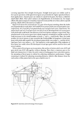
Figure 8.10 shows the sectional view of a pair of bevel gears meshing when the shafts
are perpendicular to each other. AOP and BOP are pinion pitch cone and gear pitch cone,
respectively. AO P and BO P are pinion back cone and gear back cone, respectively. The
1
2
pinion back cone AO P and gear back cone BO P canbedeveloped into twosectorgears
2
1
with pitch radii as the back cone distance of the bevel pinion and gear, respectively. Sup-
plement teeth to the sector gears form whole imaginary virtual gears and the number of
teeth increases to the virtual number of teeth z and z , respectively. Thus, the tooth
v1
v2
profiles of a bevel pinion or gear resemble the tooth profiles of imaginary virtual spur
gears with pitch radii equal to the developed pinion back cone radius r and the devel-
bv1
oped gear back cone radius r [6]. This similarity is also applicable to the midpoint of
bv2
bevelgearfacewidthwhere thedeveloped virtualspurgearwillbeusedfor forceand
stress analysis.
When a pair of bevel gears are in operation, the surface of pinion pitch cone AOP and
gear pitch cone BOP roll together without slipping. They share a common apex at the
shaft axis intersection O. Since the pitch cones of mating gears have coincident apexes,
the mounting of bevel gears is critical for achieving satisfactory performance. Proper
mounting is realized by adjusting mounting distance, which is the distance from the
end surface of the pinion hub to the apex of pitch cone O.
K A
R O d m1 d 1
δ 1 O 1
b δ 2
r bv1
B O 1
P
N 1
N 2 P
α
d m2
d 2
r bv2
O 2
O 2
Figure 8.10 Geometry and terminology of bevel gears.