
Page 214 - Analysis and Design of Machine Elements
P. 214
Analysis and Design of Machine Elements
192
8.4.1.3 Virtual Number of Teeth
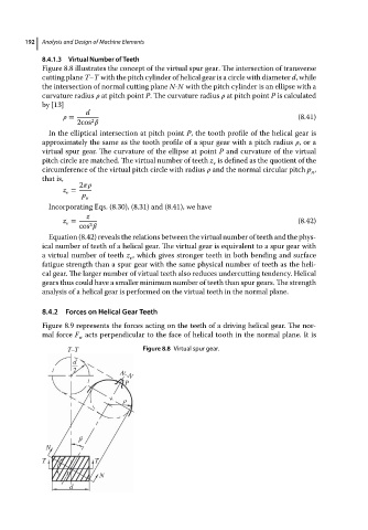
Figure 8.8 illustrates the concept of the virtual spur gear. The intersection of transverse
cutting plane T–T with the pitch cylinder of helical gear is a circle with diameter d, while
the intersection of normal cutting plane N-N with the pitch cylinder is an ellipse with a
curvature radius at pitch point P. The curvature radius at pitch point P is calculated
by [13]
d
= (8.41)
2
2cos
In the elliptical intersection at pitch point P, the tooth profile of the helical gear is
approximately the same as the tooth profile of a spur gear with a pitch radius ,ora
virtual spur gear. The curvature of the ellipse at point P and curvature of the virtual
pitch circle are matched. The virtual number of teeth z is defined as the quotient of the
v
circumference of the virtual pitch circle with radius and the normal circular pitch p ,
n
that is,
2
z =
v
p n
Incorporating Eqs. (8.30), (8.31) and (8.41), we have
z
z = (8.42)
v
3
cos
Equation (8.42) reveals the relations between the virtual number of teeth and the phys-
ical number of teeth of a helical gear. The virtual gear is equivalent to a spur gear with
a virtual number of teeth z , which gives stronger teeth in both bending and surface
v
fatigue strength than a spur gear with the same physical number of teeth as the heli-
cal gear. The larger number of virtual teeth also reduces undercutting tendency. Helical
gears thus could have a smaller minimum number of teeth than spur gears. The strength
analysis of a helical gear is performed on the virtual teeth in the normal plane.
8.4.2 Forces on Helical Gear Teeth
Figure 8.9 represents the forces acting on the teeth of a driving helical gear. The nor-
mal force F acts perpendicular to the face of helical tooth in the normal plane. It is
n
T–T Figure 8.8 Virtual spur gear.
d
2
N–N
P
ρ
β
N
T T
β
P N
d