
Page 210 - Analysis and Design of Machine Elements
P. 210
188
Analysis and Design of Machine Elements
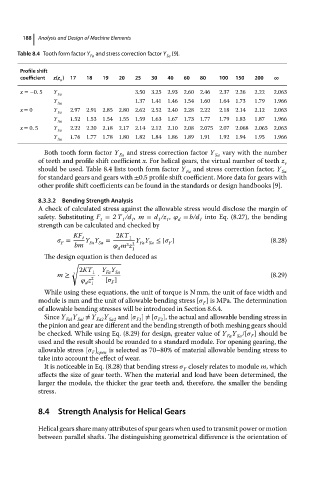
Table 8.4 Tooth form factor Y and stress correction factor Y Sa [9].
Fa
Profile shift
coefficient z(z ) 17 18 19 20 25 30 40 60 80 100 150 200 ∞
v
x =−0. 5 Y Fa 3.50 3.25 2.93 2.60 2.46 2.37 2.26 2.22 2.063
Y Sa 1.37 1.41 1.46 1.54 1.60 1.64 1.73 1.79 1.966
x = 0 Y Fa 2.97 2.91 2.85 2.80 2.62 2.52 2.40 2.28 2.22 2.18 2.14 2.12 2.063
Y Sa 1.52 1.53 1.54 1.55 1.59 1.63 1.67 1.73 1.77 1.79 1.83 1.87 1.966
x = 0. 5 Y Fa 2.22 2.20 2.18 2.17 2.14 2.12 2.10 2.08 2.075 2.07 2.068 2.065 2.063
Y Sa 1.76 1.77 1.78 1.80 1.82 1.84 1.86 1.89 1.91 1.92 1.94 1.95 1.966
Both tooth form factor Y Fa and stress correction factor Y Sa vary with the number
of teeth and profile shift coefficient x. For helical gears, the virtual number of teeth z
v
should be used. Table 8.4 lists tooth form factor Y and stress correction factor, Y
Fa Sa
for standard gears and gears with ±0.5 profile shift coefficient. More data for gears with
other profile shift coefficients can be found in the standards or design handbooks [9].
8.3.3.2 Bending Strength Analysis
A check of calculated stress against the allowable stress would disclose the margin of
safety. Substituting F = 2T /d ,m = d /z , = b/d into Eq. (8.27), the bending
t 1 1 1 1 d 1
strength can be calculated and checked by
KF 2KT
= t Y Y = 1 Y Y ≤ [ ] (8.28)
F
3 2
bm Fa Sa m z 1 Fa Sa F
d
The design equation is then deduced as
√
2KT 1 Y Y
Fa Sa
m ≥ 3 ⋅ (8.29)
z 2 [ ]
F
d 1
While using these equations, the unit of torque is N mm, the unit of face width and
module is mm and the unit of allowable bending stress [ ] is MPa. The determination
F
of allowable bending stresses will be introduced in Section 8.6.4.
Since Y Y ≠ Y Y and [ ] ≠ [ ], the actual and allowable bending stress in
Fal Sal Fa2 Sa2 F1 F2
the pinion and gear are different and the bending strength of both meshing gears should
be checked. While using Eq. (8.29) for design, greater value of Y Y /[ ] should be
Sa
Fa
F
used and the result should be rounded to a standard module. For opening gearing, the
allowablestress[ ] is selected as 70–80% of material allowable bending stress to
F open
take into accountthe effectofwear.
It is noticeable in Eq. (8.28) that bending stress closely relates to module m,which
F
affects the size of gear teeth. When the material and load have been determined, the
larger the module, the thicker the gear teeth and, therefore, the smaller the bending
stress.
8.4 Strength Analysis for Helical Gears
Helical gears share many attributes of spur gears when used to transmit power or motion
between parallel shafts. The distinguishing geometrical difference is the orientation of